Manual ST3 controller 2022
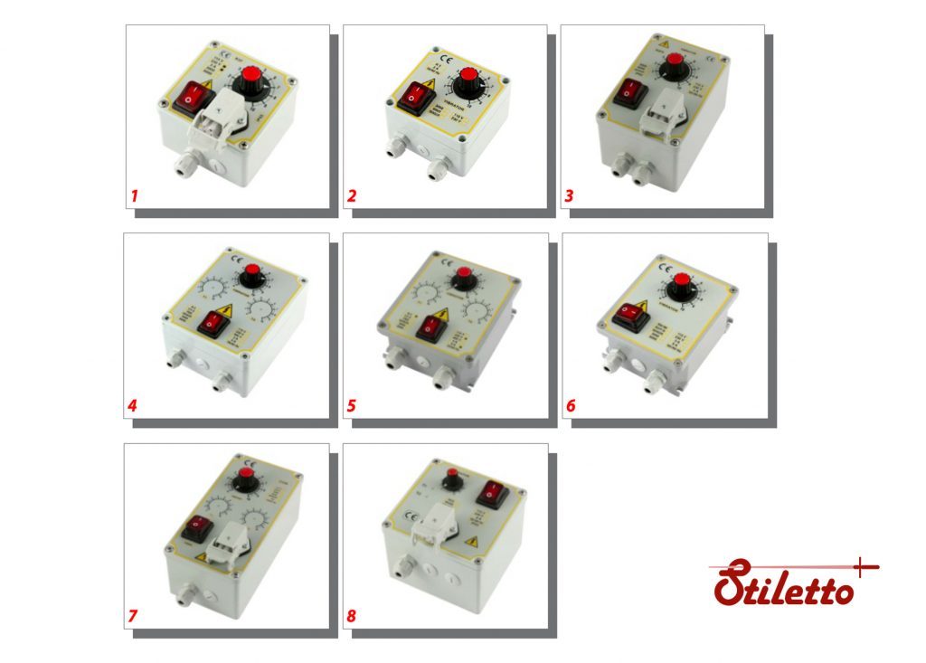
This operating instruction applies to:
This operating instruction applies to:
| Type | Box | Colour | Dimensions | Code |
|---|---|---|---|---|
| ST3 | Circuit | 80 x 95 x 35 | ST3FCX A2 STD | |
| ST3 | Fire-retardant plastic | RAL 7035 | 100 x 100 x 50 | ST3FCX Z2 STD |
| ST3 | Aluminum | RAL 7035 | 100 x 100 x 50 | ST3FCX Z2 STM |
| ST3/DIN | Circuit | 115 x 85 x 50 | ST3FCX D2 STD | |
| ST3+PRX92 | Circuit+circuit for sensor NPN/PNP | RAL 7035 | 100 x 100 x 50 | ST3P92 Z2 STD |
This equipment conforms with ecc directive 2014/30/UE (EMC – Electromagnetic Compatibility) and directive 2014/35/UE (LVD – Low Voltage Directive)
Please contact us through our contact page – Contact

Indicates an immediate threatening danger.
Non-compliance with this information can result in death or serious personal injuries (invalidity).
 Indicates a possibly dangerous situation.
Non-compliance with this information can result in death or serious personal injuries (invalidity).

Indicates a possibly dangerous situation.
Non-compliance with this information can result in damage to property or .light to medium personal injuries.

Indicates general notes, useful operator tips and operating recommendations which don’t affect safety and health of the personnel.
Before connect the equipment to the mains socket, make sure that the nameplate data match those of the mains power supply.
Only use this equipment in accordance with the porpouse for which it is designed; i.e. for regolation of the amplitude of an electromagnetic vibrator feeder. Any other use is to considered improper, therefore hazardous.
The Manufacturer cannot be held liable for any improper, incorrect or unreasonable use of the equipment, switch it off and do not tamper with it. If repair is needed, please contact the Manufacturer’s Technical.
Service Centre only, as they use original spare parts. Failure to observe the above the recommendations could impair the safety of the equipment.
All operations regarding adjustement, measurement and testing when required, must only be carried out by authorized and qualified personnel.
The Manufacturer shall accept no liability for damage to persons, animals or objects caused by work on the equipment carried out by unauthorized and unqualifield personnel.
Before switching on the equipment, connect the mains voltage, conforming to the current regulation, and the vibratory feeder.
Verifying that the installation has an appropriate ground wiring system.
TURN OFF THE POWER BEFORE OPENING.
NOTE : Don’t use the apparatus in proximity of subject zones to vibrations, or in acid and humid working environment
If vibratory feeder works bad or doesn’t work:
| Circuit Type: ST3FC | Degree Of Protection: Ip55in Box (Only Circuit Ip00) |
| Supply Voltage: 115 Or 230V ± 10% 50/60Hz | Position Of Assemblage: Horizontal Or Vertical. |
| Consumption: 1,5 W Max | Degree Of Pollution: 2 |
| Current Max: 3/4A (Rms) | Temperature Of Storage: -15 °C / + 80 °C |
| Load Min.: 50Ma Rms | Temperature Of Operation: -5 °C / + 55 °C |
| Potentiometer Of Reg.: 100K Ohm Linear | Range Of Relative Humidity: 80% Till to 31°C |
| Freq. Of Vibration: 3000/6000V/M (50Hz) 3000/7200V/M (60Hz) | Installation Class: Ii |
| Time Ramp: 0,2 Sec. Or 2 Sec. (Selectable) | Altitude: Till to 2000 Meters |
| Regulation Min.: 80V ± 30% | European Norms: EMC CE |
| Input On/Off: Free Contact - Signal Voltage 0/24V | Warranty: 1 Year (from date on circuit) |
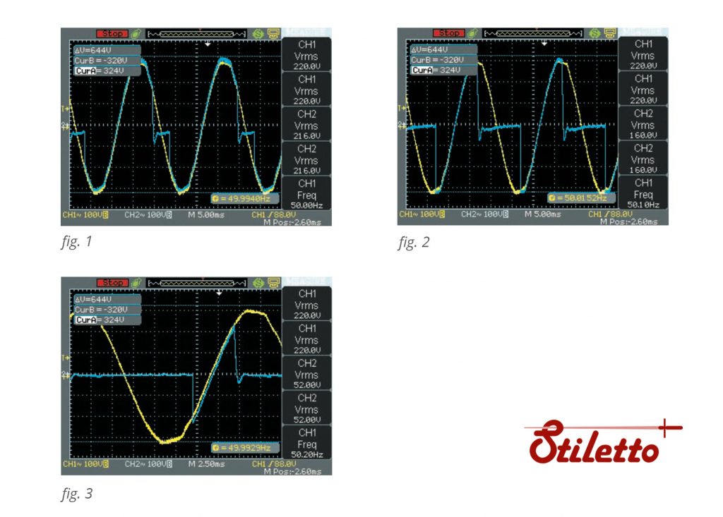
Description waveforms figures (above)
Supply controller (yellow)
Output vibrator (blue)
Frequency: 50 Hz – 3000 V/m (vibrator)
Figure statististics
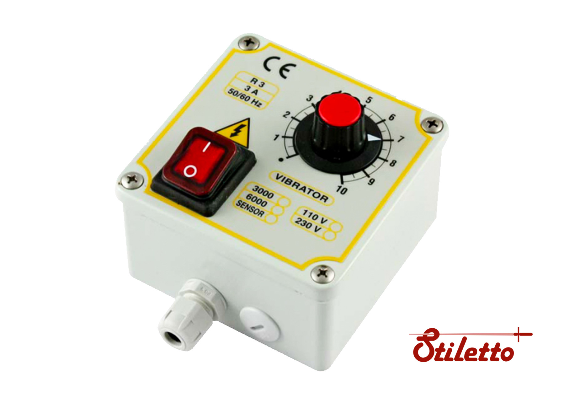
Before give voltage to the controller connect the supply voltage (clamps 2-3 CONN1), verifying that the installation has an appropriate ground wiring system and the vibrator (clamps VIBRATOR – CONN 2) of the connector (1-4 ground).
According European Norms EMC the controller have a line-filter with leakage current to ground less 1 mA.
To adjust intensity of vibration of the vibratory feeder, turn the adjustment knob (potentiometer 100K) on the box.
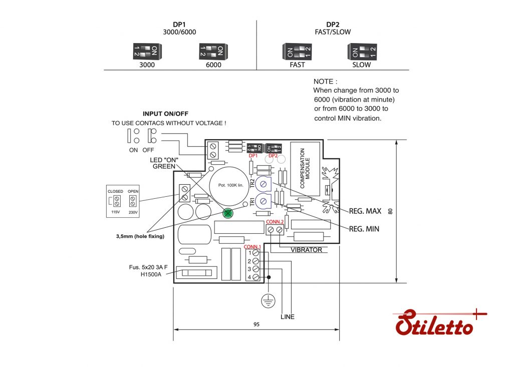
To adjust the Min./Max voltage of the vibratory feeder, proceed as follows :
MIN REG.: Turn the potentiometer to minimum, then set the minimum vibration by means of relative trimmer TR1.
MAX REG. : Turn the potentiometer to maximum, then set the maximum vibration by means of relative trimmer TR2.
N.B. : Use a small bladed screw driver in order not to damage the trimmer. Turn it in vertical direction respect to the PC board.
The vibratory feeder can be switched off by contact without voltage, using the auxiliary ON/ OFF input.
Is possible to change the time of the start ramp (slow 1 sec or fast 0,1 sec) by DP2.
Is possible to change the frequency of vibration 3000V/m-50Hz (3600V/m-60Hz) or 6000V/m- 100Hz (7200V/m-120Hz) by DP1; before switch off the voltage.
Green Led indicates Voltage ON- Fuses intact and signals damages to the entry stage of the stabilizing module.
Is possible (on request) to have nr.2 speed (high and slow speed ) with 2 potentiometers.
Note
If you use only the electronic circuit (IP00) insert and cable it in a box that could guarantee an excellent safety degree respecting the European regulation in force and isolate the terminals of the potentiometer with the rubbers provided.
Decline all responsibility for damage caused by improper use of the circuit
DESIGN AND SPECIFICATIONS ARE SUBJECT TO CHANGE WITHOUT NOTICE
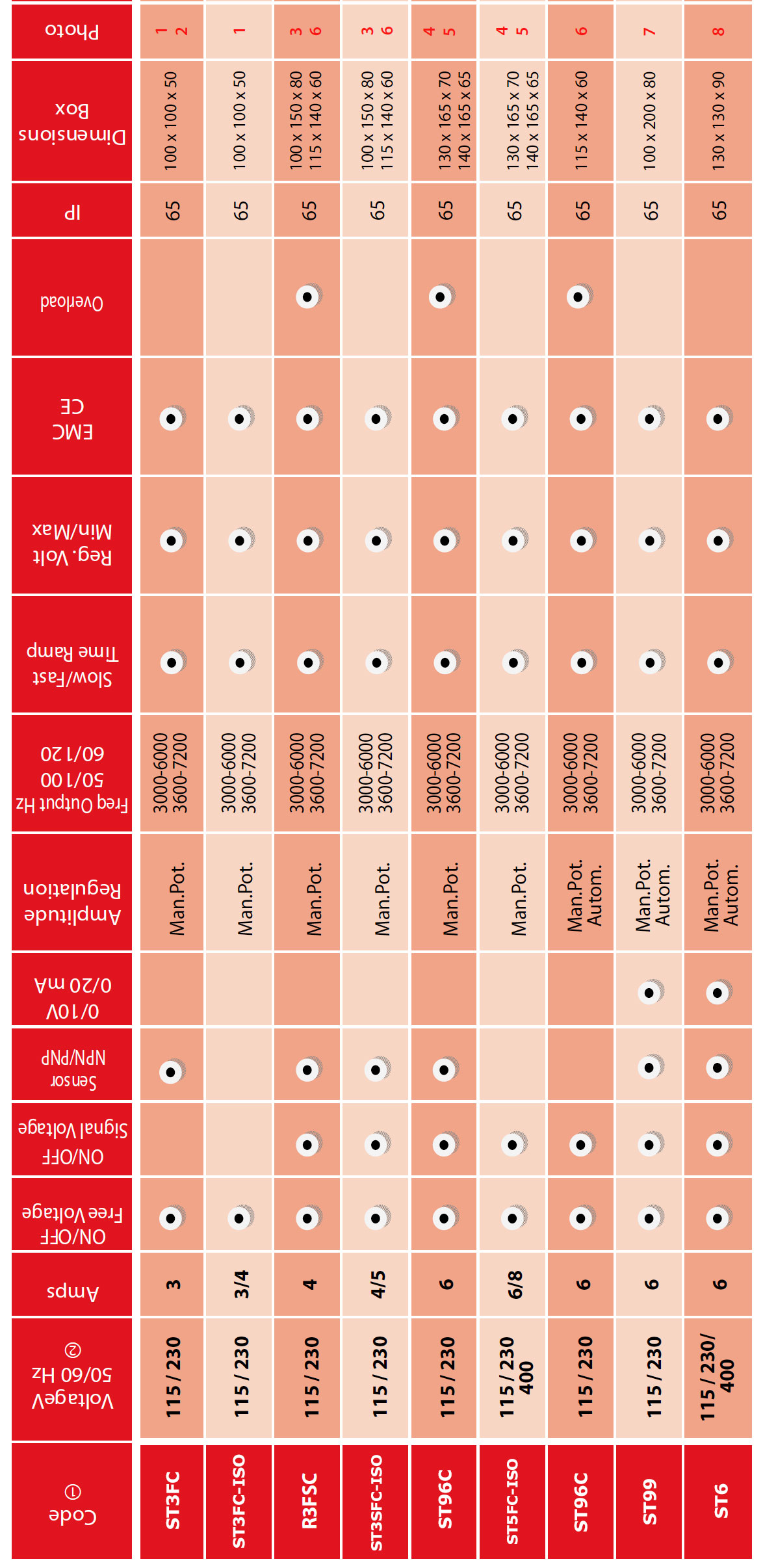
Notes:
1. All controllers are stabilized
2. Other voltage on request
3. With circuit PRX92-PRX99 inside
4. With circuit PRX07 inside
We hebben een nieuwe vacature voor Service Engineer. Ben jij de kandidaat die we zoeken?