Manual ST10/17 - ST20/17 - ST40/17 controller
This operating instruction applies to:
This operating instruction applies to:
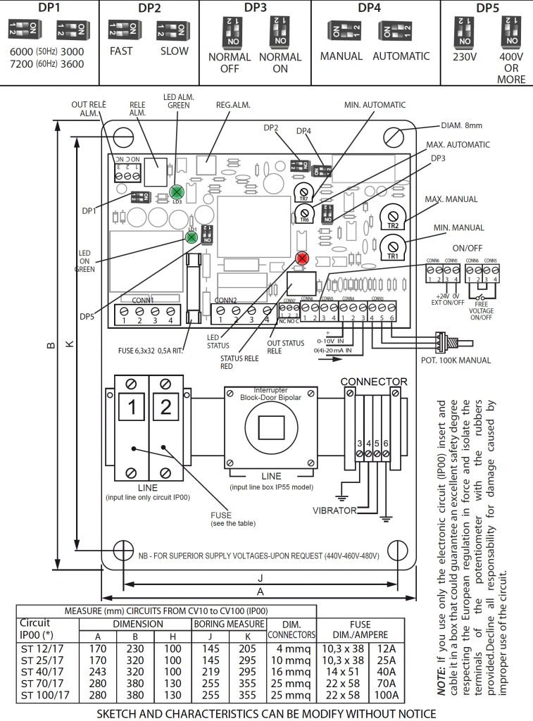
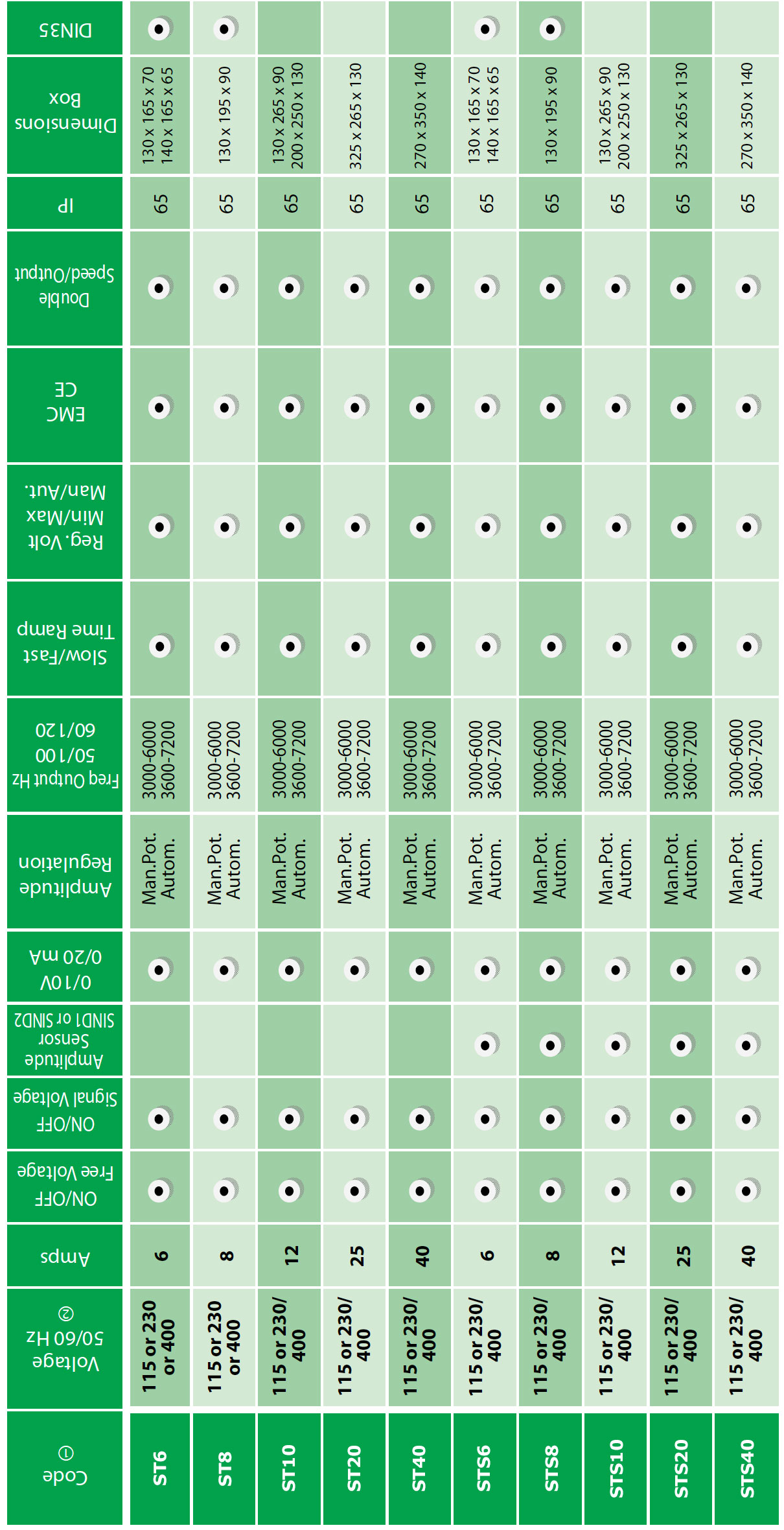
| Type | Box | Colour | Dimensions | Code |
|---|---|---|---|---|
| ST10/17 | Circuit | 230 x 170 x 100 | PV C1217 A4 STD | |
| ST10/17 | Metallic Box | Grey | 250 x 200 x 130 | PV C1217 Z4 STD |
| ST15/17 | Circuit | 230 x 170 x 100 | PV C1517 A4 STD | |
| ST15/17 | Metallic Box | Grey | 250 x 200 x 130 | PV C1517 Z4 STD |
| ST20/17 | Circuit | 170 x 320 x 100 | PV C25 17 A4 STD | |
| ST20/17 | Metallic Box | Grey | 235 x 265 x 130 | PV C2517 Z4 STD |
| ST40/17 | Circuit | 320 x 248 x 100 | PV C4017 A4 STD | |
| ST40/17 | Metallic Box | Grey | 350 x 274 x 140 | PV C4017 Z4 STD |
| ST70/17 | Circuit | 280 x 380 x 130 | PV C7017 Z4 STD | |
| ST70/17 | Metallic Box | Grey | 312 x 412 x 140 | PV C70 17 Z4 STD |
| ST100/17 | Circuit | 280 x 380 x 130 | PV C10017 Z4 STD | |
| ST100/17 | Metallic Box | Grey | 372 x 462 x 235 | PV C100 17 Z4 STD |
This equipment conforms with ecc directive 2014/30/UE (EMC – Electromagnetic Compatibility) and directive 2014/35/UE (LVD – Low Voltage Directive)
Please contact us through our contact page – Contact

Indicates an immediate threatening danger.
Non-compliance with this information can result in death or serious personal injuries (invalidity).
 Indicates a possibly dangerous situation.
Non-compliance with this information can result in death or serious personal injuries (invalidity).

Indicates a possibly dangerous situation.
Non-compliance with this information can result in damage to property or .light to medium personal injuries.

Indicates general notes, useful operator tips and operating recommendations which don’t affect safety and health of the personnel.
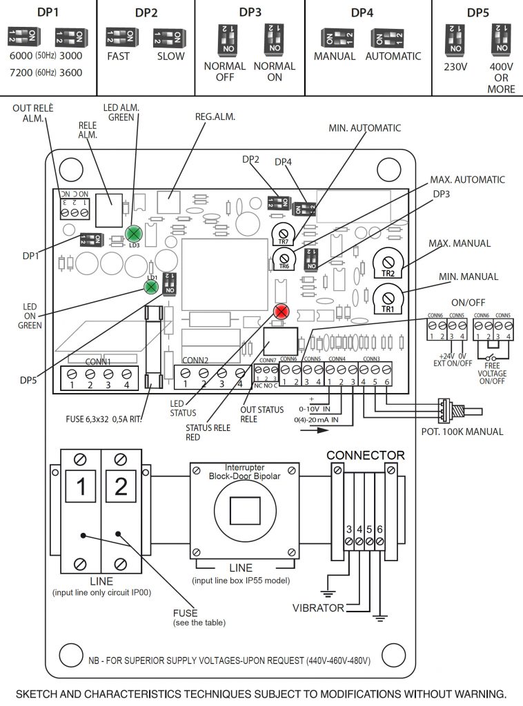
NEW FUNCTION
ST10/17 – ST20/17 – ST40/17 circuit is an evolution of the old ST10 – ST20 – ST40, circuit, specifically designed for those who use any PLC-controlled configuration (eg Static relay for ON/OFF inputs and 0/10V signals for remote control) without risk of signals interference .
The technical solutions implemented therefore make the applications safer and more protected.
A Status Relay has also been implemented, it indicates the status of the vibrator with contact in change and red LED.
Initial Start-up ST Series
Below are some general indications, in case of first use of the controller:
The step-by-step guide of the functions allows to identify the signal or the function that cause problems.
This start-up application scheme can be used both with the ST / F card and with the ST / 17 card.
Note: check that the ON / OFF comes from a contact to a clean RELAY and not from a static RELAY and that the
0/10V signal is a continuous signal and not a PWM signal.
Before connect the equipment to the mains socket, make sure that the nameplate data match those of the mains power supply.
Only use this equipment in accordance with the porpouse for which it is designed; i.e. for regolation of the amplitude of an electromagnetic vibrator feeder. Any other use is to considered improper, therefore hazardous.
The Manufacturer cannot be held liable for any improper, incorrect or unreasonable use of the equipment, switch it off and do not tamper with it. If repair is needed, please contact the Manufacturer’s Technical.
Service Centre only, as they use original spare parts. Failure to observe the above the recommendations could impair the safety of the equipment.
All operations regarding adjustement, measurement and testing when required, must only be carried out by authorized and qualified personnel.
The Manufacturer shall accept no liability for damage to persons, animals or objects caused by work on the equipment carried out by unauthorized and unqualifield personnel.
Before switching on the equipment, connect the mains voltage, conforming to the current regulation, and the vibratory feeder.
Verifying that the installation has an appropriate ground wiring system.
TURN OFF THE POWER BEFORE OPENING.
NOTE : Don’t use the apparatus in proximity of subject zones to vibrations, or in acid and humid working environment
If vibratory feeder works bad or doesn’t work:
On request is available series ST/17 with output 25 Hz or 33 Hz.
| Circuit Type: ST10/17 - ST15/17 - ST20/17 - ST40/17 - ST70/17 - ST100/17 | Input ipedance 0/10V - 0/20 mA: 50Komh-50ohm |
| Supply Voltage: 230V or 400V(till 500V) 5% 50/60Hz | Degree Of Protection: IP55 (IP65)in box (only circuit IP00) |
| Consumption: 3,5 W Max | Input ON/OFF: contact 0-24Vcc |
| Current Max: 12A/15A/25/40A/70A RMS | Position Of Assemblage: Horizontal Or Vertical. |
| Load Min.: 50Ma Rms | Degree Of Pollution: 2 |
| Potentiometer Of Reg.: 100K Ohm Linear | Temperature Of Storage: -35C / + 80C |
| Freq. Of Vibration: 3000/6000V/M (50Hz) 3000/7200V/M (60Hz) | Temperature Of Operation: -25 °C / + 50 °C |
| Time Ramp: 0,1 sec. or 1 sec. (selectable) | Range Of Relative Humidity: 80% Till to 31°C |
| Regulation Min.: 80V 30% (230V) 140V 30% (400V) | Installation Class: Ii |
| Regulation Max.: 200V - 30% (230V) 350V-30% (400V) | Altitude: Till to 2000 Meters |
| Input On/Off: Free Contact - Signal Voltage 0/24V | AUTOMATIC INPUT CONSUMPTION 0/10V: 1mA max |
| AUTOMATIC INPUT CONSUMPTION 0/10V: 0/10 1mA max |
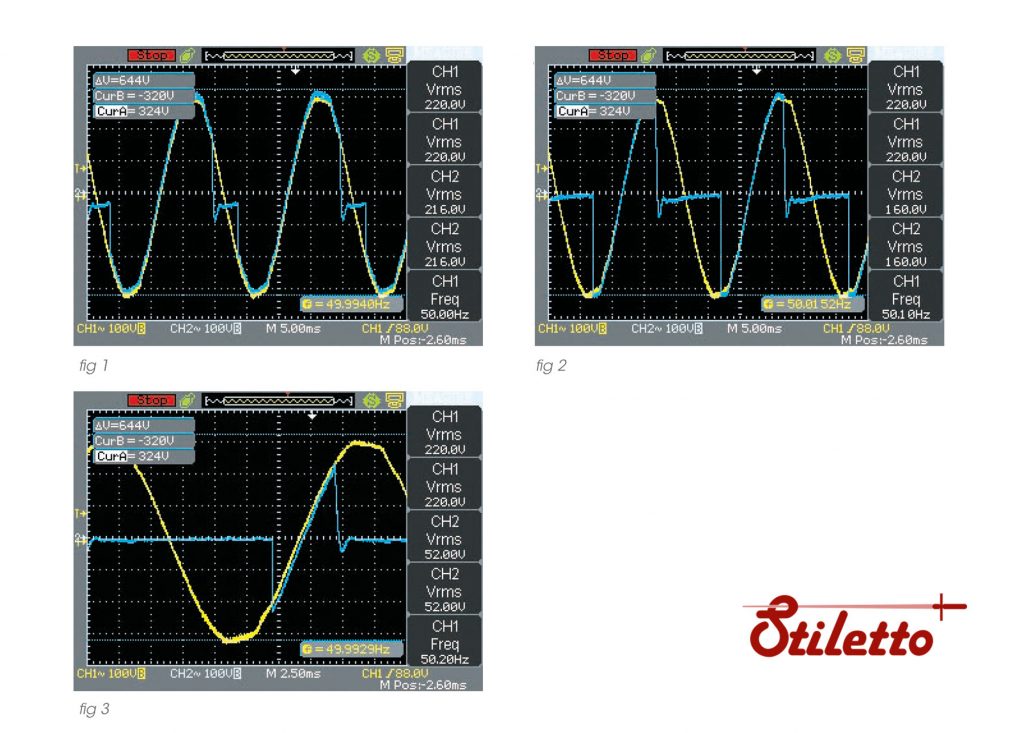
Description waveforms figures (above)
Supply controller (yellow)
Output vibrator (blue)
Frequency: 50 Hz – 3000 V/m (vibrator)
Figure statististics
Before switching on the equipment, connect the mains voltage (terminals 1-2-3), verifying that the
installation has an appropriate ground wiring system conforming to the current regulation, and the
vibratory feeder (terminals 4-5-6).
According European Norms EMC the apparatus have a line-filter with leakage current to ground less 1 mA..
The mains voltage can be selected follows:
Connect the lead to pin 1 of terminal board CONN1, and to move the DP5 on 400V for supply voltage of 400V till
500V. For supply voltage of 230V, connect the lead to pin 2 of terminal board CONN1 and to move DP5 on 230V.
To adjust intensity of vibration of the vibratory feeder, turn the adjustement knob (potentiometer 100K) on the
box. Other input voltage see MR1 – DTCVXY.
To adjust the Min./Max voltage of the vibratory feeder, proceed as follows :
MIN REG.: Turn the potentiometer to minimum, then set the minimum vibration by means of relative trimmer TR1.
MAX REG. : Turn the potentiometer to maximum, then set the maximum vibration by means of relative trimmer TR2.
N.B. : Use a small bladed screw driver in order not to damage the trimmer. Turn it in vertical direction respect to the PC board.
The vibratory feeder can be regulated with an external signal (0-10V o 0-20mA o 4-20mA). To do so, proceed as follows:
– Shift DP4 on AUTOMATIC.
– Supply an input signal, 0-10V ( 1 (+) – 2 CONN 4) or 0-20mA (4-20mA) (2 – 3 (+) CONN 4) to regulate the vibratory feeder.
The trimmers MIN (TR7) – MAX (TR6) for the automatic regulation could be used for regulate the minimum and / or the maximum voltage TR6.
The vibratory feeder can be switched off by contact without voltage, using the auxiliary ON/OFF input (4
CONN5/1 CONN6 and close 2 CONN6-3 CONN5). Also with 0/24V (+3/-4 CONN5) move DP3 to change the
logic.
It is possible to change the time of the start ramp (slow 1 sec or fast 0,1 sec) by jumper DP2.
Is possible to change the frequency of vibration 3000V/m-50Hz (3600V/m-60Hz) or 6000V/m- 100Hz (7200V/m-120Hz) by DP1; before switch off the voltage.
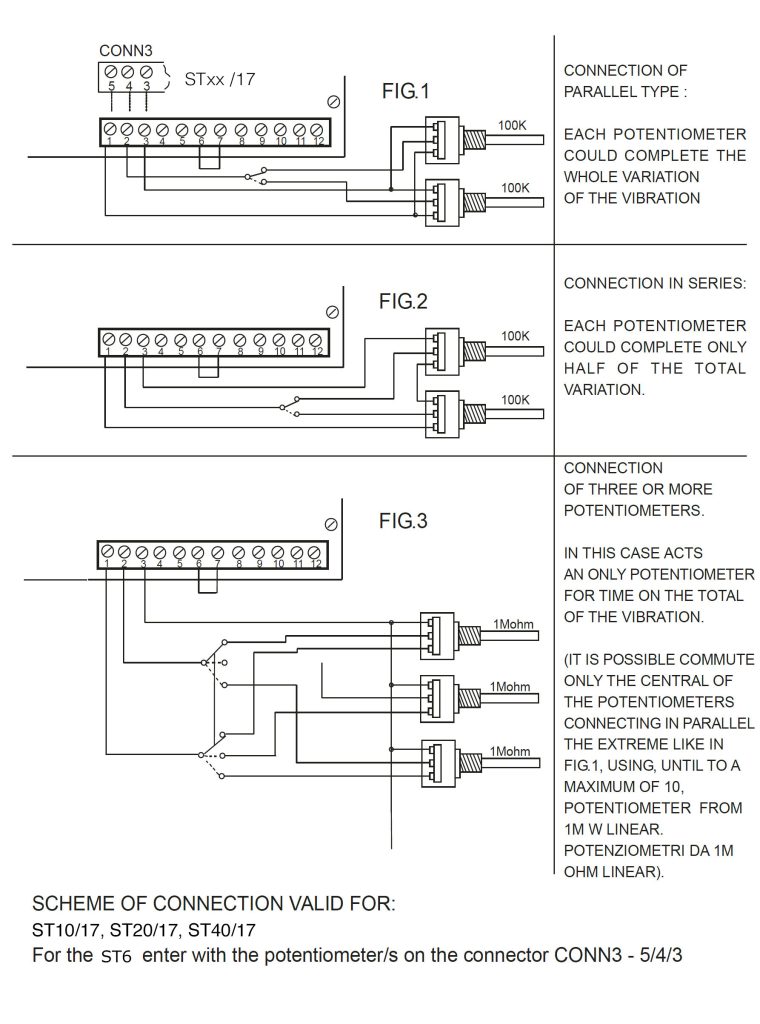
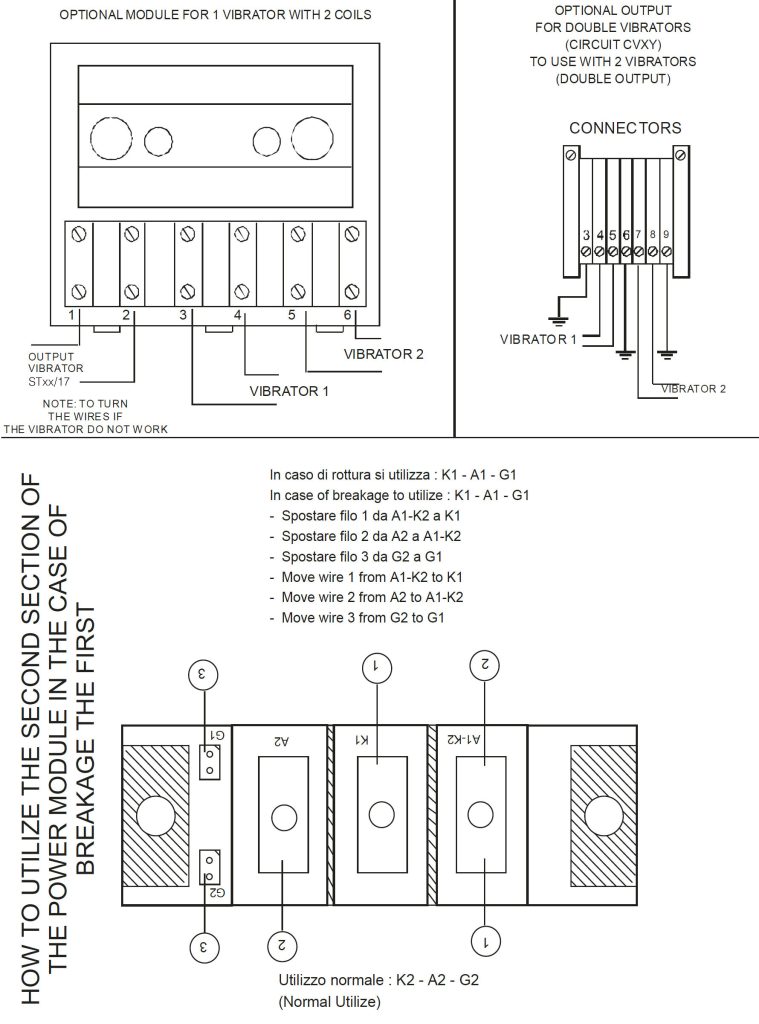
It is possible, on request, to have double speed (High and Low speed) with 2 potentiometers. See catalogue sheet.
 Alarm ON Vibrator
Upon specific request, a relay signalling the functioning status of the vibrator can also be supplied. Such relay switches over solely within an active window included between the ignition of the circuit and a maximum vibration level that can be regulated by a trimmer (ALM REG).The relay cannot be activated outside these limits. Any electrical anomaly of either the vibrator or the circuit would cause the interruption of the excitation of the relay (GREEN Led OFF) making it possible to alarm the equipment and therefore avoiding any negative consequence. Anomalies of this sort can include, for example: breakage of the vibrator bobbin, breakage of the circuit triac, breakage of the stabilizer module, tampering with the trimmer that sets the maximum vibration, causing excessive vibrations over and above the set limit.
Note
If you use only the electronic circuit (IP00) insert and cable it in a box that could guarantee an excellent safety degree respecting the European regulation in force and isolate the terminals of the potentiometer with the rubbers provided.
Decline all responsibility for damage caused by improper use of the circuit
DESIGN AND SPECIFICATIONS ARE SUBJECT TO CHANGE WITHOUT NOTICE
We hebben een nieuwe vacature voor Service Engineer. Ben jij de kandidaat die we zoeken?